Steel expands by about 12 µm per metre per kelvin. A 60 m outdoor tray run spanning a 60 K seasonal swing therefore changes length by roughly 43 mm, and without a place for that movement to go, it goes into bowed rails, sheared bolts and buckled covers. Expansion joints absorb it; fixed anchors control where it goes. NEMA VE 1 covers metallic cable tray systems including expansion provisions, and IEC 61537 covers the mechanical classification and load tests for tray and ladder systems.
Why Thermal Movement Matters on a Tray Run
Every rail is a long, thin structural member. When it cannot extend longitudinally, the restrained force builds until the weakest element yields: an anchor bolt shears, a splice plate slot elongates, or the rail bows sideways between supports. The damage is usually attributed to “poor installation” when it is actually an omitted movement provision.
Three movement sources have to be handled:
- Ambient temperature swing. Seasonal and day/night variation. On an exposed rooftop or pipe rack, the rail temperature is not the air temperature — dark surfaces in full sun run well above ambient, so the effective swing is larger than a weather-station figure suggests.
- Building or structure movement. Structural expansion joints, settlement and wind sway. A tray crossing a building expansion joint must accommodate that movement independently of its own thermal movement.
- Cyclic movement at terminations. Where tray meets fixed equipment — switchgear, transformer, motor — movement is transferred into the termination unless the last section is detailed to allow it.
Coefficients and the Sizing Calculation
| Material | Coefficient of linear expansion α | Movement per 30 m at ΔT = 50 K | Notes |
|---|---|---|---|
| Carbon steel (galvanised or painted) | ≈ 11.7–12.5 × 10⁻⁶ /K | ≈ 18 mm | Most common tray material; use 12 × 10⁻⁶ /K for estimates |
| Austenitic stainless steel (304 / 316) | ≈ 16–17.5 × 10⁻⁶ /K | ≈ 25 mm | About 40 % more movement than carbon steel |
| Aluminium | ≈ 23 × 10⁻⁶ /K | ≈ 35 mm | Nearly double carbon steel; check every support and clamp |
| FRP / GRP (polyester or vinyl ester) | ≈ 18–25 × 10⁻⁶ /K (resin and fibre dependent) | ≈ 27–38 mm | Wide spread between products; the manufacturer’s figure is essential |
The sizing equation is straightforward:
ΔL = α × L × ΔT
Worked example (illustrative only — confirm inputs with the project specification and the manufacturer’s data):
- Material: hot-dip galvanised carbon steel, α = 12 × 10⁻⁶ /K
- Section length between fixed points: L = 60 m = 60 000 mm
- Installation temperature: 20 °C
- Design temperature range: −10 °C to +50 °C, giving a total swing ΔT = 60 K
- ΔL = 12 × 10⁻⁶ × 60 000 × 60 = 43.2 mm
That 43.2 mm is the full travel the expansion device must accommodate, and it is split between expansion and contraction relative to the installation temperature. At 20 °C installation, the rail can extend about 21.6 mm and contract about 21.6 mm. This is why the installation temperature matters: an expansion gap set on a cold morning with no allowance for summer expansion will be fully closed by midsummer, and the joint stops working.
Manufacturers publish a gap-setting chart against installation temperature for each expansion splice. Use it, photograph the set gap, and record the ambient temperature at the time of setting.
Types of Expansion Provision
Sliding expansion splice plate
Two overlapping rail sections joined by a plate with slotted holes, allowing longitudinal movement while maintaining vertical alignment. Bolts are tightened to a value that permits sliding rather than clamping — this is a common site error: installers torque the bolts to the standard splice value and lock the joint.
Expansion coupling / expansion joint section
A purpose-made fitting with a telescoping or sliding interface, usually rated for a stated travel in each direction. Preferred where movement is large or where the run crosses a building expansion joint with significant structural movement.
Sliding and guided supports
Some designs leave the tray free to slide on the support, with a controlled fixed point at one location per expansion section. Sliding supports should use a low-friction interface and must not be converted into anchors by a well-meaning installer adding a clamp.
Flexible expansion at the cable level
The tray moving is only half the problem: the cables inside move too. Maintain the manufacturer’s minimum bend radius, avoid strapping cables rigidly to the tray at every support near an expansion joint, and leave a service loop where a cable leaves the tray for fixed equipment.
Application Scenario / Case Analysis: Exposed Pipe-Rack Run at an Industrial Plant
Scenario constraints
A 180 m straight run of galvanised ladder tray on an outdoor pipe rack carries power and control cables between two buildings. The rack is steel, exposed to full sun, with an ambient range of −5 °C to +45 °C and a surface temperature that runs higher in summer. The run crosses the building expansion joint at the midpoint and has intermediate supports at 2 m centres.
Selection approach
- Split the run into expansion sections of 30–40 m, which is a widely used spacing for outdoor metallic tray; treat it as a starting point, not a rule, and confirm against the manufacturer’s travel rating for the chosen device.
- Place one fixed anchor per section, ideally near the midpoint, and let movement occur away from it in both directions. All other supports in the section are sliding or guided.
- At the building expansion joint, use an expansion device sized for the structural movement stated by the structural engineer, plus the tray’s own thermal movement — these add, they do not overlap.
- Specify slotted-hole splice plates with a stated clearance, and write the bolt torque value for expansion joints separately from the standard splice torque value.
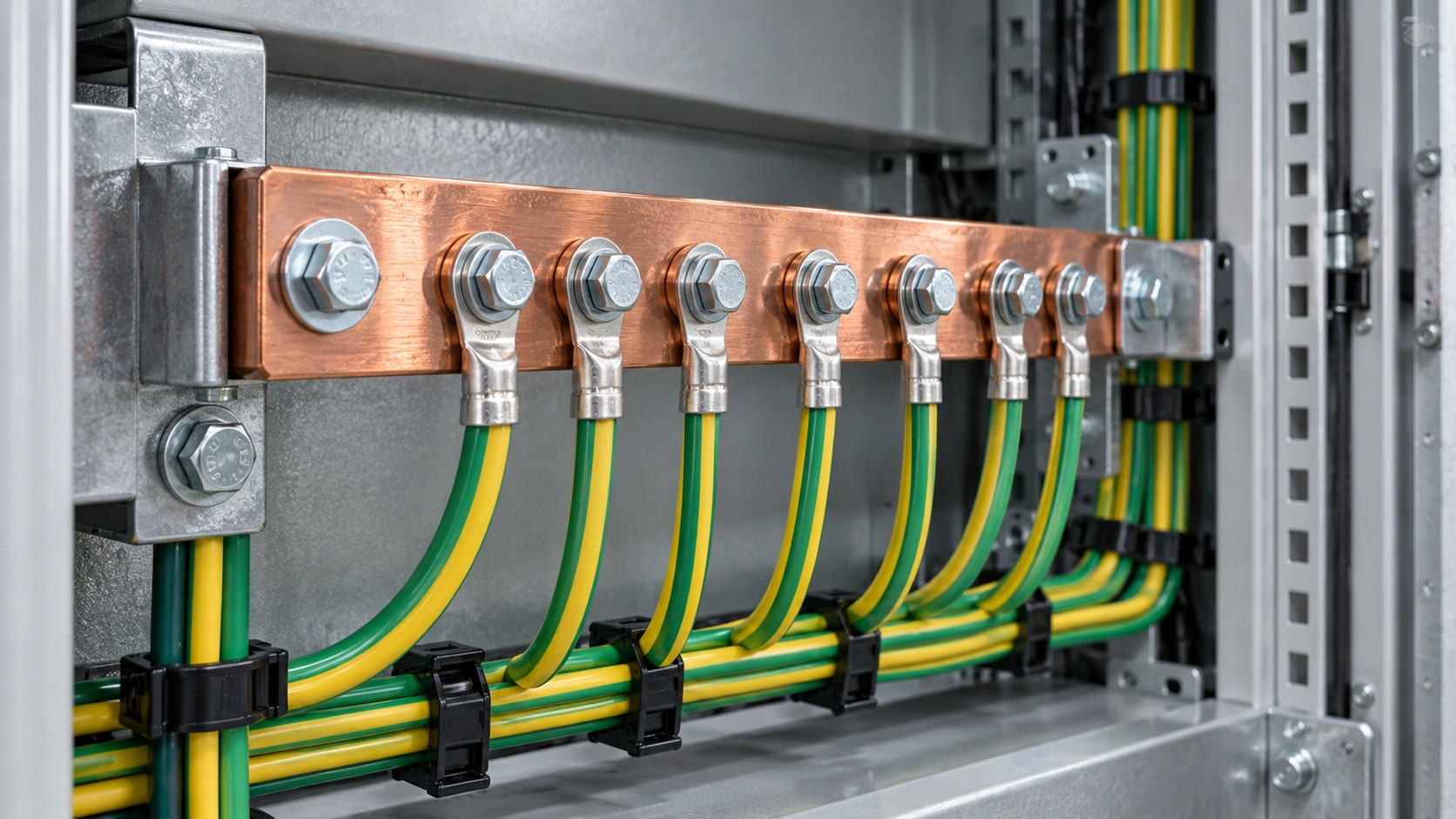
- Maintain the earthing and bonding path across every gap with a flexible bonding jumper sized to the project’s bonding requirements, since a sliding joint does not guarantee electrical continuity.
Common mistakes
- Bolting expansion joints tight “to make it rigid” — this removes the whole function of the fitting.
- Setting the gap without recording the installation temperature, so summer expansion has nowhere to go.
- Welding the tray to the support at both ends of an expansion section, creating two fixed points and a guaranteed bow.
- Fitting covers across an expansion joint as a continuous length; covers need their own movement allowance.
- Omitting the bonding jumper, and relying on the mechanical joint for the protective conductor path.
- Applying a carbon-steel expansion allowance to an aluminium or stainless run, under-sizing the device by 40 % or more.
Acceptance checkpoints
- Record expansion-joint locations, device travel rating, set gap and installation temperature in the as-built file, with photographs.
- Confirm the fixed-point anchors are identifiable on site and that all other supports allow movement.
- Verify electrical continuity across each expansion joint with a low-resistance ohmmeter and record the value against the project’s stated acceptance criterion.
- Check bolt torque on expansion joints against the specific value for sliding joints, not the standard splice value.
- Re-inspect after the first full seasonal cycle: look for elongated holes, rail bow, cover buckling and any change in the gap.
Selection Key Points
- Establish the temperature range at the rail, not just at the weather station — sun-exposed dark steel runs hotter than ambient air.
- Identify the material and use the correct α; aluminium moves nearly twice as much as carbon steel.
- Define one fixed point per expansion section and make every other support free to move.
- Cross building expansion joints with a device sized for structural movement plus thermal movement.
- Set the gap against the installation temperature using the manufacturer’s chart, and record it.
- Size and fit bonding jumpers so continuity survives the movement.
- Keep cable management flexible at expansion points — minimum bend radius and service loops.
Quality Inspection Points
- Material and coating verification on the tray and on the expansion fitting; the fitting should match the corrosion protection of the run.
- Dimensional check of slot length and hole clearance against the required travel.
- Sliding-function check by hand before the cables are pulled: the joint must move freely.
- Support-type verification: fixed anchors marked, sliding supports unclamped.
- Continuity measurement across each joint, recorded.
- Documentation of the set gap, installation temperature and the manufacturer’s gap-setting chart reference.
Supplier Evaluation
Ask for the travel rating of the expansion device in both directions, the gap-setting chart, the bolt torque value specific to the sliding joint, and confirmation that the fitting’s corrosion protection matches the tray system. Ask whether the device has been tested with the tray system under load — a fitting that slides freely on the bench may bind under a loaded rail. Suppliers who cannot state a travel rating in millimetres are specifying by catalogue photograph rather than by calculation.
Comparison Table: Where Each Provision Is Used
| Provision | Typical travel capacity | Where it is used | Watch out for |
|---|---|---|---|
| Slotted splice plate | Small to moderate (clearance dependent) | Short runs, moderate swings, indoor | Over-torquing locks the joint |
| Telescoping expansion coupling | Larger, as rated by the manufacturer | Long outdoor runs, high swings | Travel must exceed calculated ΔL with margin |
| Building expansion joint crossing | Structural movement + thermal movement | Any tray crossing a structural joint | Additive movement is often underestimated |
| Guided / sliding support | Unlimited within the section | All supports except the fixed anchor | Extra clamps turn them into anchors |
| Flexible bonding jumper | Follows the movement | Across every discontinuity | Size and material compatibility |
FAQ
1. How often should expansion joints be installed?
There is no universal spacing. Calculate ΔL for the material, length and temperature range, then place devices so each section’s movement stays within the device’s rated travel. For outdoor metallic tray, 30–40 m is a common starting spacing pending that calculation.
2. Does IEC 61537 specify thermal expansion requirements?
IEC 61537 covers classification and mechanical tests for cable tray and ladder systems. Thermal movement is generally handled through project design and manufacturer guidance, and in North America through NEMA VE 1 for metallic tray systems. Confirm which framework your project is specified under.
3. Can I just leave the bolts loose at every joint?
No. Loose standard splices lose alignment and electrical continuity. Use purpose-made expansion devices at defined locations and torque standard splices to the manufacturer’s value.
4. Do aluminium trays need more expansion joints?
Yes, roughly twice the allowance of carbon steel, since α is about 23 × 10⁻⁶ /K against about 12 × 10⁻⁶ /K. Re-run the calculation; do not reuse a steel-based spacing.
5. What happens if the gap is set at the wrong temperature?
If set cold without allowance, the joint closes fully in summer and the run is effectively rigid, transferring force into supports and splices. Always use the manufacturer’s temperature chart and record the installation temperature.
6. Do covers need expansion provisions too?
Yes. A cover fixed across an expansion joint will buckle or tear its fixings. Use matching cover expansion pieces or leave a designed break.
7. How is electrical continuity maintained across an expansion joint?
With a flexible bonding jumper sized to the installation’s bonding requirements. A sliding mechanical joint is not a reliable protective conductor path; measure and record continuity across every joint.
Talk to BANGE About Tray Layout and Expansion Design
Send your run length, material, support spacing and site temperature range, and we will return the calculated movement, recommended expansion-joint locations and device ratings. Contact BANGE Electric for layout support.
Requirements may vary by application, market, and applicable standard.