Copper and aluminium busway both comply with IEC 61439-6; the difference is physics and money. Copper at 100 % IACS has a resistivity of about 0.017241 Ω·mm²/m at 20 °C, against roughly 0.028264 Ω·mm²/m for electrical-grade aluminium (about 61 % IACS). Matching ampacity therefore needs about 1.5 to 1.6 times the aluminium cross-section — but the finished conductor still weighs roughly half as much. The deciding factors are usually weight, joint reliability and material price, not conductivity alone.
The Numbers That Drive the Choice
| Property | Copper (Cu-ETP / CW004A) | Aluminium (1350 / 6101 type) | Practical consequence |
|---|---|---|---|
| Resistivity at 20 °C | ≈ 0.017241 Ω·mm²/m (IEC 60028 reference, 100 % IACS) | ≈ 0.028264 Ω·mm²/m (≈ 61 % IACS) | Aluminium needs ≈ 1.64× the cross-section for equal DC resistance |
| Temperature coefficient α | ≈ 0.00393 /K | ≈ 0.00403 /K | Aluminium resistance climbs slightly faster with temperature |
| Density | ≈ 8.96 g/cm³ | ≈ 2.70 g/cm³ | Equal-resistance aluminium conductor weighs ≈ 48–50 % of copper |
| Coefficient of linear expansion | ≈ 17 × 10⁻⁶ /K | ≈ 23 × 10⁻⁶ /K | Aluminium moves more with temperature; joint design and expansion provisions matter more |
| Surface oxide | Copper oxide — relatively conductive, easily removed | Aluminium oxide — hard, electrically insulating, reforms within seconds | Aluminium joints need surface preparation and compounding |
| Creep under bolt pressure | Low | Higher | Aluminium joints benefit from Belleville/spring washers and scheduled re-torque checks |
Two corrections matter in practice. First, equal DC resistance is not equal ampacity: the larger aluminium section radiates heat from a bigger surface, so the cross-section ratio for equal continuous current is usually nearer 1.5 than 1.64 — but only the manufacturer’s verified rating for that specific enclosure type is authoritative. Second, skin and proximity effects at 50/60 Hz reduce the effective conducting area in a large bar, so a very wide aluminium bar does not scale linearly; the rating comes from type testing, not from arithmetic.
Why Joints Decide Whether an Aluminium Busway Succeeds
Aluminium fails at the joint, not in the middle of a bar. The failure mechanism is well understood:
- Oxide reformation. Aluminium oxide forms within seconds of cleaning and is an electrical insulator. Joints must be abraded immediately before assembly, ideally under a layer of oxide-inhibiting compound that excludes air.
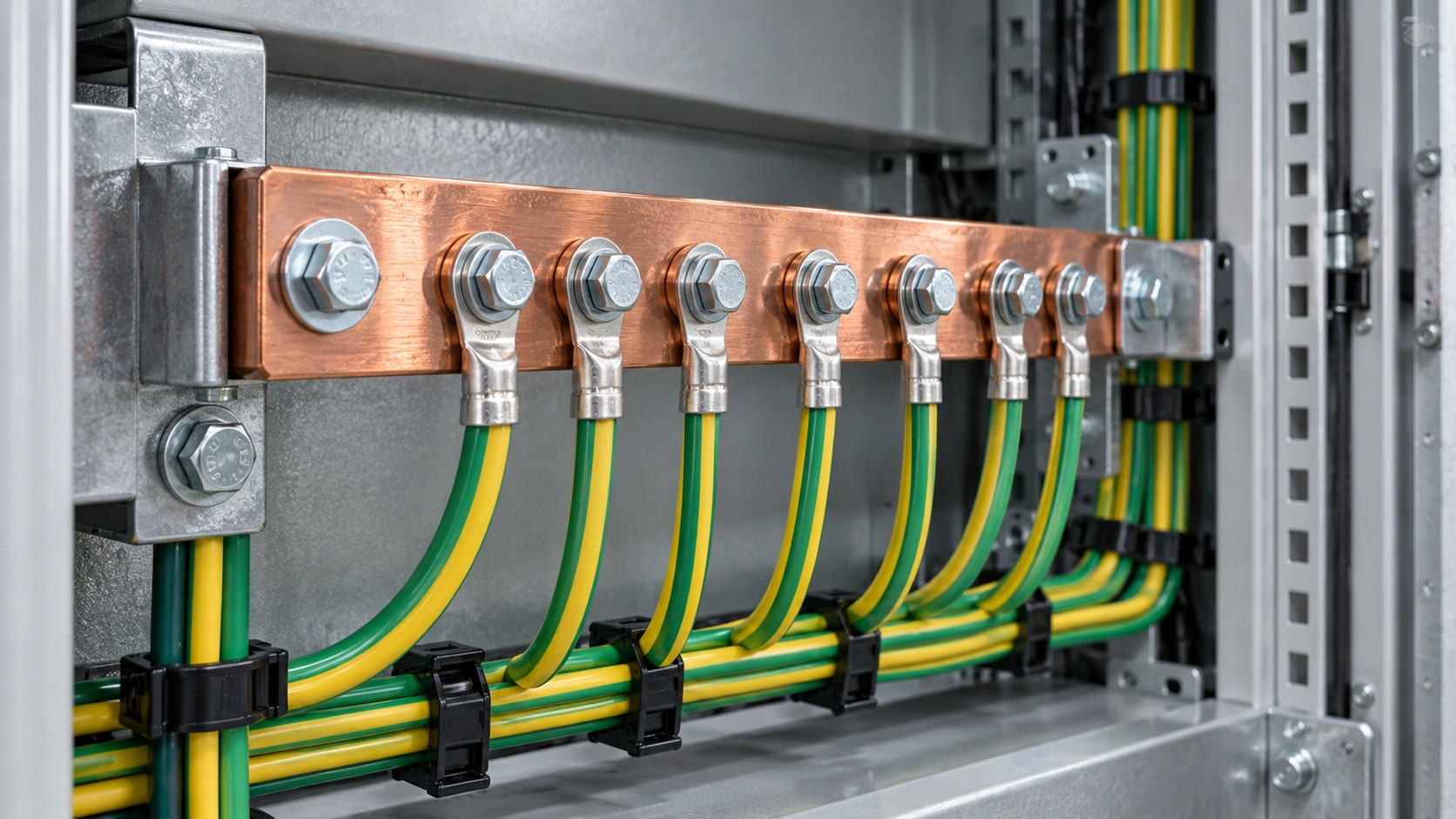
- Creep and relaxation. Under sustained bolt pressure, aluminium deforms plastically more than copper, so bolt preload decays and contact resistance rises. Belleville or conical spring washers maintain pressure across the thermal cycle.
- Thermal expansion. With ≈ 23 × 10⁻⁶ /K against ≈ 17 × 10⁻⁶ /K for copper, an aluminium joint cycles through a larger dimensional swing. Where aluminium meets copper, the differential movement has to be absorbed by the joint design.
- Galvanic corrosion. Aluminium and copper in direct contact in the presence of an electrolyte form a galvanic couple, with aluminium as the sacrificial anode. Bi-metallic transition washers or plating on the contact face are standard mitigation.
Contact surfaces are therefore normally plated. Tin plating is common, with typical thickness in the single-digit micrometre range depending on the manufacturer’s process; silver plating is used where higher operating temperatures are expected. Where an aluminium busway terminates onto copper cable lugs, specify a tested bi-metallic transition — not a plain bolted stack.
Verification sits in IEC 61439-6. The assembly must be type-tested for temperature rise at its rated current, with joints included in the test arrangement, against the limits in IEC 61439-1 for busbars and connections and for accessible surfaces. Confirm that the rating you are quoted comes from a test on the actual conductor material and cross-section, not from a calculation or from a copper test applied to an aluminium variant by analogy.
Cost: Material, Installation and Life Cycle
Material price is volatile. Copper has typically traded at around three to four times the price of aluminium per tonne on the LME, but that ratio moves; check current figures at the time of enquiry rather than relying on a historical number. On a conductor-material basis alone, aluminium usually wins for equal ampacity. The comparison narrows once the rest of the project is included:
- Weight and handling. At roughly half the conductor weight, aluminium reduces crane time, support structure loading and manual handling on long vertical runs.
- Cross-section and space. Copper wins where the shaft or ceiling void is tight, because the same current needs a smaller bar.
- Voltage drop. Resistance per metre is a manufacturer datum. On long runs the larger aluminium section is often competitive once resistance — not ampacity — is the governing constraint.
- Maintenance. Aluminium joints need documented re-torque intervals as part of the maintenance plan. If the site has no thermographic survey programme, that risk should be priced in.
Application Scenario / Case Analysis: High-Rise Riser Shaft Feeding Tenant Floors
Scenario constraints
A 30-storey building distributes 1000 A from a basement substation up a riser shaft of about 110 m, with a tap-off unit on each floor, a fire barrier at every slab penetration, and a shaft cross-section that cannot be enlarged. Installation is by hand through a shaft door, so each length has to be carried by two people. Voltage drop from substation to the top floor must stay within the limit set by the applicable wiring rules.
Selection approach
- Model both options on resistance, not just ampacity. Take the manufacturer’s resistance and reactance per metre for each material and cross-section, then compute voltage drop at the design current and power factor.
- Worked example (illustrative only — use the manufacturer’s data and the project specification): sandwich busway, 1000 A, 110 m, cos φ = 0.90 (sin φ ≈ 0.436). If the datasheet gives R = 0.045 mΩ/m and X = 0.028 mΩ/m, then ΔU ≈ √3 × I × L × (R·cos φ + X·sin φ) = 1.732 × 1000 × 110 × (0.045 × 0.9 + 0.028 × 0.436) mΩ ≈ 1.732 × 1000 × 110 × 0.05270 × 10⁻³ ≈ 10.0 V, or about 2.5 % of a 400 V nominal system. IEC 60364-5-52 recommends the total voltage drop between the origin of the installation and the point of utilisation should not exceed 4 %; some national rules use separate feeder and branch limits, so confirm which applies.
- If both options meet the drop limit, weigh the shaft width against the handling weight: aluminium reduces the load on each support and on the installation crew, copper keeps the cross-section smaller.
- Specify the joint system explicitly for aluminium: plated contact faces, spring washers, compound, torque value and re-torque interval, plus a bi-metallic interface at copper terminations.
- Add a thermographic survey to the commissioning and annual maintenance programme regardless of material.
Common mistakes
- Comparing price per kilogram instead of price per ampere-metre. Aluminium is cheaper per kg but needs more of it.
- Applying a copper rating to an aluminium bar by ratio calculation instead of using the tested value.
- Bolting aluminium conductors directly to copper lugs without a bi-metallic transition, then finding green corrosion products at the joint within a season.
- Using flat washers under the bolt head on aluminium joints, so preload is lost to creep after the first thermal cycles.
- Forgetting that the tap-off contacts and the plug-in interfaces must also be rated and tested for the conductor material in use.
Acceptance checkpoints
- Confirm the IEC 61439-6 type-test report identifies the conductor material, cross-section and enclosure type actually supplied.
- Record joint torque values with a calibrated tool, and record the plating specification on contact faces.
- Where aluminium meets copper, verify the bi-metallic interface is present and documented.
- Measure insulation resistance and complete the dielectric verification before energisation, then take a baseline thermal scan at design load.
- Write the re-torque and re-scan intervals into the maintenance contract, along with the acceptance temperature-rise criterion from IEC 61439-1.
Selection Key Points
- Fix the governing constraint first: ampacity, voltage drop, available space, or weight. Material choice follows from that.
- Use tested ratings for the exact material and enclosure, never ratios applied across materials.
- Specify the joint system in the same document as the conductor: plating, washer type, compound, torque, re-torque interval.
- Require a bi-metallic transition wherever aluminium meets copper.
- Compare total installed cost including supports, handling and maintenance, not conductor material alone.
- Confirm the short-circuit withstand rating (Icw and Ipk) for the chosen conductor, since mechanical strength under fault current is material-dependent.
Quality Inspection Points
- Material certificate for the conductor, with conductivity or resistivity stated and traceable to the melt.
- Cross-section and dimensional check against the approved drawing.
- Plating thickness verification on contact faces, using the method agreed with the manufacturer.
- Temperature-rise test record, or design verification by comparison with a tested reference design as permitted by IEC 61439-1.
- Joint resistance or millivolt-drop measurement on a sample basis, recorded in the test file.
- Visual check for burrs, scratches and flatness on contact surfaces before assembly.
Supplier Evaluation
Ask three questions and require documentary answers. First: can you show the IEC 61439-6 type-test report for the aluminium version at this rating, not only for the copper version? Second: what is the specified joint system — plating thickness, washer type, compound, torque value and re-torque interval? Third: what bi-metallic transition do you supply at copper terminations, and is it type-tested as part of the assembly? A manufacturer that answers all three with documentation is a materially different supplier from one that answers with assurances.
BANGE Electric manufactures both copper and aluminium conductor busway, and can run the ampacity and voltage-drop comparison for your route before you commit to a material. See the busway systems range or contact the engineering team with your one-line diagram and route length.
FAQ
1. How much bigger does an aluminium busbar need to be?
For equal DC resistance, about 1.64 times the copper cross-section, based on the resistivity ratio. For equal ampacity the ratio is usually nearer 1.5 because the larger section dissipates heat better. Use the manufacturer’s tested rating rather than a ratio.
2. Is aluminium busway reliable?
Yes, when the joint system is engineered for it: plated contact faces, spring washers to counter creep, oxide-inhibiting compound, and documented re-torque intervals. Most field problems trace to joints assembled as though the conductor were copper.
3. Can aluminium and copper be connected directly?
Not without mitigation. The two metals form a galvanic couple in which aluminium corrodes. Use a tested bi-metallic transition piece or plated interfaces, and keep the joint dry.
4. Does aluminium busway need more maintenance?
It needs a documented maintenance regime, not necessarily more work: a periodic thermographic survey and torque verification. Sites with no survey programme should budget for introducing one.
5. Which material has better short-circuit performance?
Both are supplied to a declared Icw and Ipk per IEC 61439-6. The mechanical strength and the support spacing under fault current differ by material and cross-section, so compare the tested withstand values for the specific product rather than assuming copper is superior.
6. Is aluminium always cheaper?
On conductor material, usually. On total installed cost it depends on cross-section, support structure, handling and the maintenance regime. Copper can win where space is tight or where the maintenance programme is minimal.
7. What does IEC 61439-6 require for temperature rise?
The assembly must be verified at rated current with joints included, against the limits in IEC 61439-1 for busbars and connections and for accessible surfaces. The verification can be by test or by comparison with a tested reference design under the conditions set out in IEC 61439-1.
Talk to BANGE About Conductor Selection
Send your rated current, route length, installation geometry and the applicable wiring rules, and we will return a copper-versus-aluminium comparison with tested ratings, voltage-drop figures and the joint specification for each option. Contact BANGE Electric to begin.
Requirements may vary by application, market, and applicable standard.